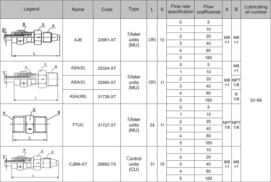
●Meter Units (MU) & Control Units (CU)
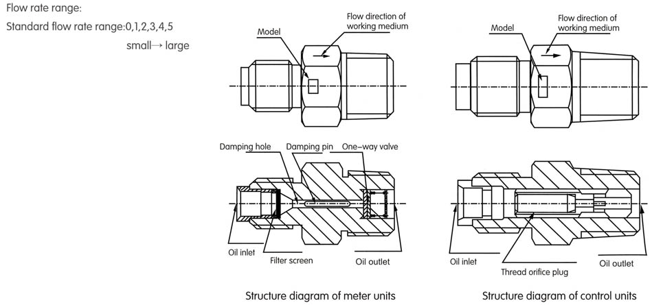
Meter units (MU), which have tubular structure, have built in filter screen and one-way valve. The flow is controlled based on the throttle principle of damping hole, and MU is applicable to SLR periodic lubrication system. Control units (CU) has tubular structure, and the flow is controlled with the spiral orifice plug, and CU is applicable to SLR continuous lubrication system. The lubricating oil can be proportionally delivered to the lubrication points according to the specification of the meter units and control units. The meter units and control units can be directly connected to the lubrication points.
The meter units or control units within the specification of four-flow rate shall be selected as possible for the same lubrication system.
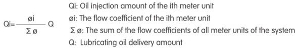
●Formula of oil delivery amount: |

